
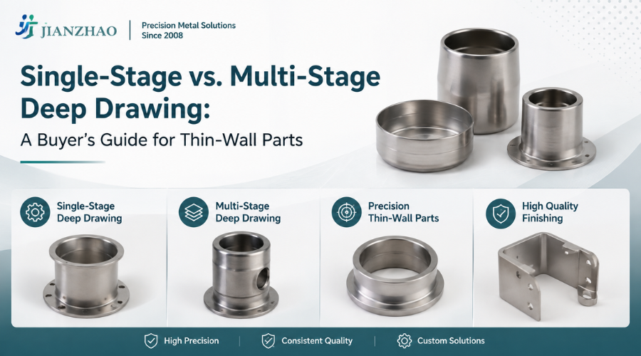
In parts manufacturing, some decisions must be made before production begins. Choosing the right manufacturing method is one of them, and it happens earlier than many buyers realize. Even before a purchase order is placed or a supplier is chosen, deciding between single-stage and multi-stage deep drawing is already affecting your part’s cost and production risks. If you make the right choice at the quoting stage, the rest of the process is much smoother. If not, you may face rework, tolerance issues, and unexpected tooling costs.
Demand for thin-wall precision components is growing in automotive, medical devices, and electronics. Tighter shapes, lighter materials, and stricter tolerances are now standard, not premium, requirements. In this environment, working with a precision metal stamping manufacturer who can match the process to your part’s complexity from the beginning is not just a preference. It is a technical necessity.
This guide offers a clear, practical way to compare single-stage and multi-stage deep drawing for thin-wall parts. Engineering buyers who need to choose between the two will find this blog helpful. We provide a step-by-step approach to help you make the best choice for your application.
Deep drawing is a sheet metal forming process in which a flat metal blank is pulled into a die cavity with a punch, creating a hollow, three-dimensional shape without cutting or joining the material. This produces a seamless part with controlled wall geometry, making it the preferred method for thin-wall components in demanding industries. Challenges that make process selection necessary for parts' dimensional accuracy. As material is drawn into the die, it is subjected to radial tensile stress and circumferential compressive stress simultaneously. In thin-wall applications, this stress concentration is amplified.
The consequences of mismanaging it include:
Material thinning: Too much thinning at the punch radius weakens the part wall and makes it more likely to fracture.
Wrinkling: Compressive stress in the flange area causes surface instability.
Springback: Elastic recovery after forming alters final dimensions, especially in high-strength materials
Fracture: Exceeding the material's forming limit at any stage results in scrap
Deep drawing stands out from other stamping methods for thin-wall parts because it keeps the material continuous. There are no seams, welds, or joins. This is crucial for parts where structural strength and surface finish are essential. However, the process only works as promised if you choose the right stage setup for your part’s shape and material.
In single-stage deep drawing, the entire forming operation is completed in one press stroke. The blank is drawn to its final depth and geometry in a single die set, without intermediate annealing or reforming steps.
This method works well when the part’s shape allows it. Specifically, it is effective when the draw ratio, which is the relationship between the blank diameter and punch diameter, stays within a manageable range, usually below 2.0. It also works when the part depth is not too great compared to its diameter, allowing a single stage to produce clean, consistent parts efficiently.
Simple cylindrical or rectangular cup geometries
Shallow to moderate draw depths
Materials with good ductility, such as mild steel, aluminum, and soft copper alloys
Lower to mid-volume production runs where tooling costs are limited.
Programs with short lead times and simple part designs.
Draw ratio above 2.0: Single-stage drawing struggles when draw ratios go above 2.0. It also does not work well when you need very consistent wall thickness.
Complex part geometry: When the part shape is more complicated and includes features like shoulders, flanges, or uneven cross-sections, single-stage drawing shows its limits. In these cases, a single draw can put too much stress on the material, leading to scrap or parts that look fine but fail under testing.
Multi-stage deep drawing splits the forming process into a series of steps. At each stage, the blank diameter is reduced a bit more, and the part depth increases. Between these steps, the material is annealed to restore its ductility before the next draw.
This step-by-step approach makes multi-stage drawing better for complex, high-precision thin-wall parts. Each stage stays within the material’s forming limits, so wall thickness is more uniform and the surface stays in better condition. This also improves dimensional accuracy.
Deep-to-diameter ratios that exceed single-stage capability
Complex shapes with stepped profiles and tight-radius shoulders. These are common in medical device housings, aerospace enclosures, and micro-components where tight tolerances are required.
High-volume production where per-unit scrap reduction justifies tooling investment
Materials that need careful work hardening control during each forming stage
The tooling investment is significantly higher. A multi-stage die set requires precision engineering at every stage, and tooling development lead times are longer. For lower-volume programs or parts with simpler geometries, the economics rarely justify the additional upfront commitment.
It is also a less forgiving process to modify once tooling is cut. Design changes after tool completion are expensive.
|
Criteria
|
Single-Stage
|
Multi-Stage
|
Single-Stage Pros/Cons
|
Multi-Stage Pros/Cons
|
|
Tooling Cost
|
Lower | Higher |
Pro: Lower upfront investment / Con: Limited to simpler geometries
|
Pro: Enables complex part production / Con: High initial tooling commitment
|
|
Lead Time
|
Shorter | Longer |
Pro: Faster to market / Con: May compromise quality on complex parts
|
Pro: Superior output quality / Con: Longer development timeline |
|
Draw Ratio Capability
|
Up to 2.0 | Up to 5.0+ (progressive) |
Pro: Adequate for standard geometries / Con: Restricts part design complexity
|
Pro: Handles deep, complex geometries / Con: Requires precise stage engineering
|
|
Wall Thickness Consistency
|
Moderate | High |
Pro: Acceptable for low-tolerance parts / Con: Inconsistent on thin-wall specs
|
Pro: Tight, predictable wall uniformity / Con: Any stage misalignment impacts all subsequent stages
|
|
Surface Finish
|
Good | Excellent |
Pro: Sufficient for non-critical surfaces / Con: May require secondary finishing
|
Pro: Minimal secondary finishing needed / Con: Higher tooling precision required |
|
Scrap Rate
|
Higher on complex parts | Lower |
Pro: Acceptable on simple geometries / Con: Elevated scrap on demanding applications
|
Pro: Lower material waste at volume / Con: Higher cost impact if stage parameters are mis-set
|
|
Minimum Viable Volume
|
Low to mid | Mid to high |
Pro: Viable for short runs / Con: Unit economics plateau early
|
Pro: Strong unit economics at scale / Con: Not cost-effective for low-volume programs |
|
Best-Fit Industries
|
Consumer electronics, general hardware, simple enclosures | Medical, aerospace, automotive, micro-components |
Pro: Broad applicability / Con: Not suited for regulated, tight-tolerance sectors
|
Pro: Ideal for high-specification regulated industries / Con: Over-engineered for commodity parts |
Use this selection framework before you discuss anything with the supplier. It will sharpen your brief and give your metal stamping components supplier the information they need to provide an accurate process recommendation and quote.
|
Selection Criteria
|
Single-Stage Is Better
|
Multi-Stage Is Better
|
Notes
|
|
Draw Ratio (Blank dia. / Punch dia.)
|
Below 2.0 | Above 2.0 | Higher ratios require progressive stress redistribution |
|
Part Depth to Diameter Ratio
|
Shallow to moderate | Deep relative to diameter | A depth-to-diameter ratio above 0.5 typically favors multi-stage |
|
Wall Thickness Tolerance
|
+/- 0.1mm or looser | Tighter than +/- 0.1mm | Multi-stage delivers tighter, more repeatable wall uniformity |
|
Part Geometry Complexity
|
Simple: cylindrical, rectangular cups | Complex: stepped, flanged, re-entrant profiles | Complex profiles require sequential material conditioning |
|
Material Type
|
High-ductility: mild steel, soft aluminum | Work-hardening alloys: stainless steel, brass, titanium | Harder materials benefit from inter-stage annealing |
|
Annual Production Volume
|
Under 50,000 units | Above 50,000 units | Multi-stage tooling economics improve significantly at scale |
|
Tooling Budget
|
Limited upfront capital | Higher upfront investment acceptable | Consider total cost of ownership, not just tooling cost |
|
Regulatory / Quality Requirements
|
General commercial tolerances | Medical, aerospace, or automotive grade | Regulated industries typically mandate multi-stage precision |
|
Time to First Article
|
Urgent | Standard development timeline acceptable | Single-stage reaches first article faster |
Choosing the process is only part of the decision. The other part is picking a manufacturing partner who can deliver reliably to your specifications.
• Press tonnage range and bed size relative to your blank dimensions
• In-house tooling design and fabrication capability. Outsourced tooling adds a variable you cannot fully control.
• Experience handling your specific alloy, especially if you use stainless steel, titanium, or copper alloys that need controlled forming conditions
• Demonstrated experience with thin-wall parts at your target wall thickness range
• Dimensional inspection using CMM or optical measurement systems
• Wall thickness verification at defined measurement points
• Surface integrity assessment
• First Article Inspection (FAI) report before bulk production
A skilled precision metal stamping manufacturer does more than just take your drawing and start production. They review your design for manufacturability, point out tolerance risks before tooling begins, and suggest stage configurations. If a supplier does not offer DFM feedback at the quoting stage, they lack the needed expertise.
Single-stage and multi-stage deep drawing are not just production methods. They are complementary tools, each suited to specific part needs. As an engineering buyer, your job is not to pick a favorite but to consider your volume, part geometry, and tolerances, then match the process to those needs. This requires clarity and enough technical knowledge to ask the right questions.
The best approach is not just having a list of preferred vendors. Instead, involve the right manufacturing partner early in the design stage, before drawings are finalized, before tooling is set, and before a process decision turns into a production problem that takes months to fix.
Aluminum enclosures protect electronics, control systems, and industrial equipment. It's
READ FULLChina remains one of the largest suppliers of stamped metal products. Buyers should fami
READ FULLAluminum enclosures are the most basic foundation of almost every tech or electric devic
READ FULL

Have a question or need a quote? Fill out this form and our team will get back to you quickly!


